Thanks Mark. I'll try to bring this back to how it relates to the Next.
Normally you wouldn't call the physical wiring between the stick and the DE-9 socket a protocol, just a wiring. But in the case of Sega MegaDrive/Genesis, it kinda is. In the regular Atari type wiring we're all used to, there's a GND ground pin and and a separate input pin for all the directions and buttons, and the "protocol" is for the direction/button switches to be normally open, but closed when activated, shorting the individual pin to GND. But in Sega, one of the pins is an output pin that has a clock signal on it. The stick is supposed to watch that clock signal and divide it up into a repeating pattern of two or eight cycles, and depending on which step of the repeating pattern it thinks it is on, short the pins that correspond to that step to GND. In that way, far more buttons and directions can be used than there are separate pins for. You could call this a state machine for multiplexing signals. There used to be a nice public page decscring how the eight steps worked, but it's disappeared off the web. This one has copied most of the info, but has some unrelated arduine stuff in too:
https://jonthysell.com/2014/07/26/readi ... h-arduino/
So. The Next physical side
always operates with a 6 button Sega wiring and protocol, whichever software protocol the CPU is using to read it. But not all the software protocols can read all six buttons, or ever could in classic Spectrums. I believe we have the Next set so that Kempston 1 and 2 can read buttons B (main fire) and C, and all the other ones except MD1 and MD2 can only read button B (main fire). MD1 and 2 are the same as Kempston 1 and 2, except that all eight bits of the port can be read for extra buttons. Because there are more Sega buttons than bits in an 8bit byte, the additional buttons (Mode, X, Y and Z) can be read with
nextreg 178.
Reading the Sega protocol details, it is clear that Sega can also operate in 1 or 2 button mode, if the stick detects there is nothing going on with the clock signal on the Select output pin. And sticks that don't know about the the Select output pin ignore it. This effectively collapses it down to something very close to standard 1 button Atari wiring. The differences are that Atari machines usually had +5V on pin 7, and they had analogue paddles on pin 5 and 9. Sega has Select output pin on pin 7, +5V on pin 6, and second fire (C) on pin 9. So, for the subset of 1 button Atari joysticks that don't need power (no autofire etc), they work just fine in Sega machines and the Next. In fact this is the vast majority of 80s Spectrum sticks. apart from those ghastly nonstandard Amstrad Sinclair SJS-1 stick Mark mentions.
This is the Next (and Sega) physical wiring.
That pinout also has details of the UART mode. It came about like this. The Next has two internal fast UARTs (up to 2,000,000 baud), one to talk to the internal ESP-01 or ESP-12f wifi modem, and one to talk to the internal Raspberry Pi Zero accelerator. Devs and hardware hobbyists pretty soon found ways to use the UARTs with
wired serial cables too, for dev tools like PDS, or for sending files or other data around. But as the connections are all internal, and using the ESP connector for wired serial stops you using it for the ESP, we added the ability to plug a serial cable into one of the joystick ports. That Select output pin on pin 7 is now very useful, as it can be used for serial TX. Any of the other input pins are suitable for RX so we chose pin 9. And the only other pin serial needs is GND on pin 8.
There is a physical multiplex chip on all Next boards, which means there is only one set of FPGA GPIO pins connected to the directions and buttons, with an additional GPIO pin that can switch the mux chip between left and right socket. Because the mux chip is hardsoldered, it means there is a hard limitation of a single output pin shared between both sockets, so you can't have two UARTs connected to joystick sockets at the same time, or one UART and one Sega stick. You can have two Sega sticks because the same Select clock signal can drive both sticks at the same time.
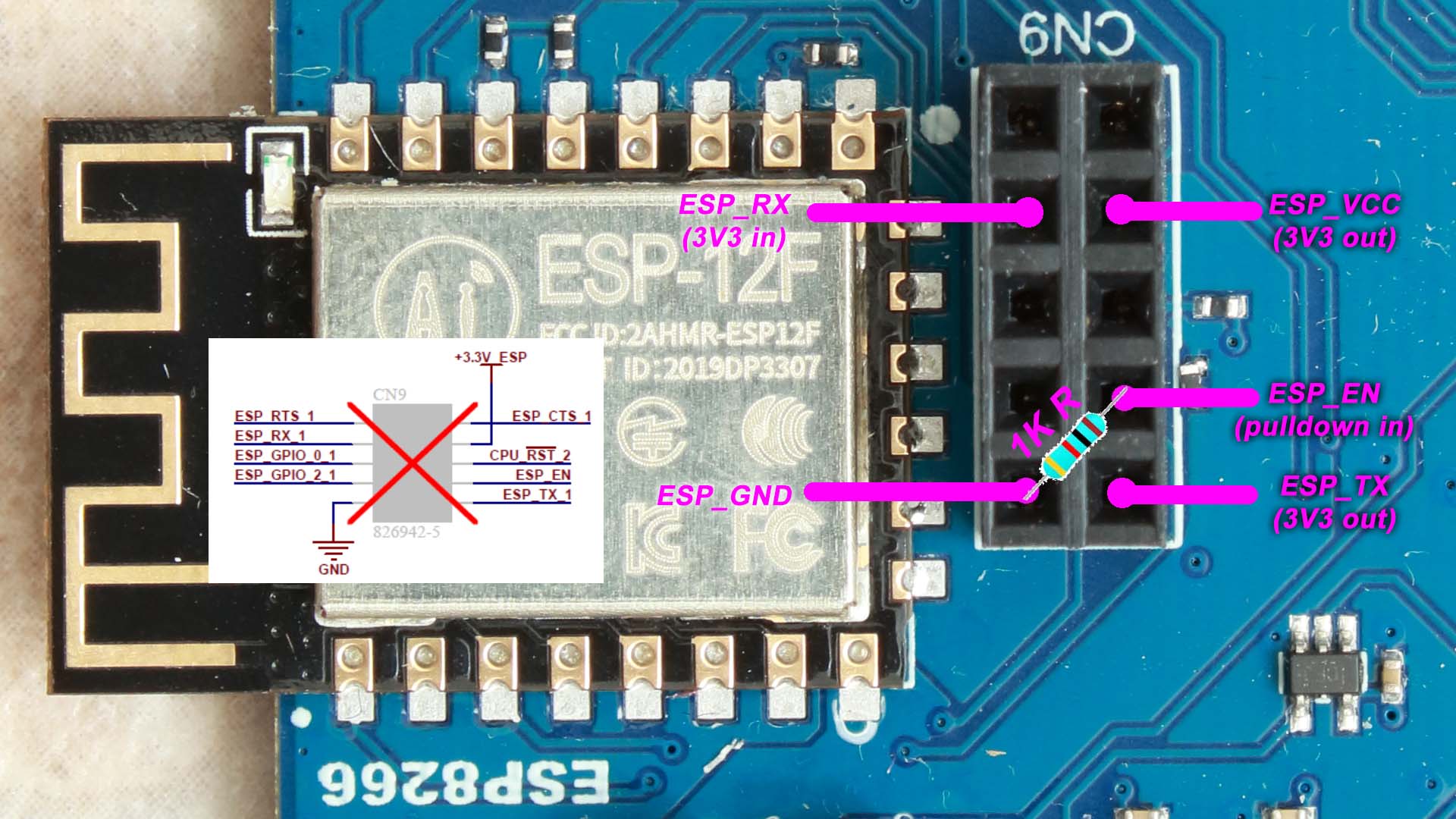
That limitation of not having two independent output pins led us to add something to the ks2 board, so that a wired serial and ESP can be connected internally at the same time. The ESP-12f is soldered in on ks2 boards, so the mechanism is to pull the ESP's EN pin low by connecting it to GND through a 1K resistor. This disables the ESP and allows the signals on the CN9 pin header to reach the FPGA, so a serial cable on CN9 can talk directly to the UART. Simply disconnecting the resistor and unplugging hte serial cable at the PC end allows the ESP back into the circuit. A similar arrangement can be done for ks1 boards, although it needs a piggyback adaptor board so that serial cable, resistor and ESP can all plug into the ks1 board's CN9.
Either left or right sockets can be switched into UART mode by writing a 111 values to
nextreg 5. ESP and Pi UARTs can be operated with
ports 0x153B, 0x163B 0x133B and 0x143B, whether in joystick mode or not.
So that's how the Next physical side works. The software protocol side being switchable is best understood by visualizing a classic Spectrum with a Kempston interface, SInclair interface 2, Cursor interface and Sega interface (they didn't exist for Spectrums back in the 80s) all plugged into the back in a big chain. All of them with two sockets, and with two rotary A/B/C/D selector switches deciding which interface is turned on for the left side and the right side. Such a thing would have been unworkable in the 80s, and people would have just unplugged everything when they wanted to switch interfaces. In fact most people only owned one interface, which is why the games were mostly written to support all the interfaces, switchable on the main menu. The Next has no such trouble having all the hardware inside the FPGA and case at once, and using aconceptual A/B/C/D selector switches in
nextreg 5.
Kempston 2 is not really a thing outside of modern hobby hardware btw. JoeFish invented it, I think, by rewiring a Kempston interface so that it responded to I/O port $1F instead of port $3F. That way he was able to set up some four player joystick gaming sessions. Fast forward a few years, and the Next team was looking for a way to have twin joystick games that still used the full keyboard (Sinclair and Cursor protocols both fake numeric keypresses). We looked at Protek (interfaces are quite rare out in the wild) but the port it uses conflicted with something else already built into the Next. So we adapted Jason's port $1F thing. It's pretty much only used for Next-specific games, but there are a small handful of classic games like Bomb Munchies that support it too.
The remaining confusion is terminology. Kempston is a company, who made Competition Pro joysticks, and joystick addons with the IN $31 software protocol, and is often used to mean a subset of the Atari wiring protocol. Atari is a company, a family of consoles (not all of which were wired the same as the 2600), a defacto wiring standard (with caveats for which pin power is on and what might be on the analogue paddle pins instead). Interface can mean hardware addon, or a common communication method between two different things. I like to call joystick interfaces addons instead of interfaces, and think of them as two back-to-back interfaces with a controller in between translating from one interface to the other. One interface speaks the Atari wiring standard, and the other interface puts data on the Z80 address bus for various addresses when the /IORQ and /RD pins are asserted low. Even controller is an ambiguous term, as it can mean a device like a CPU or logic circuit controlling things, or a joystick on a console.