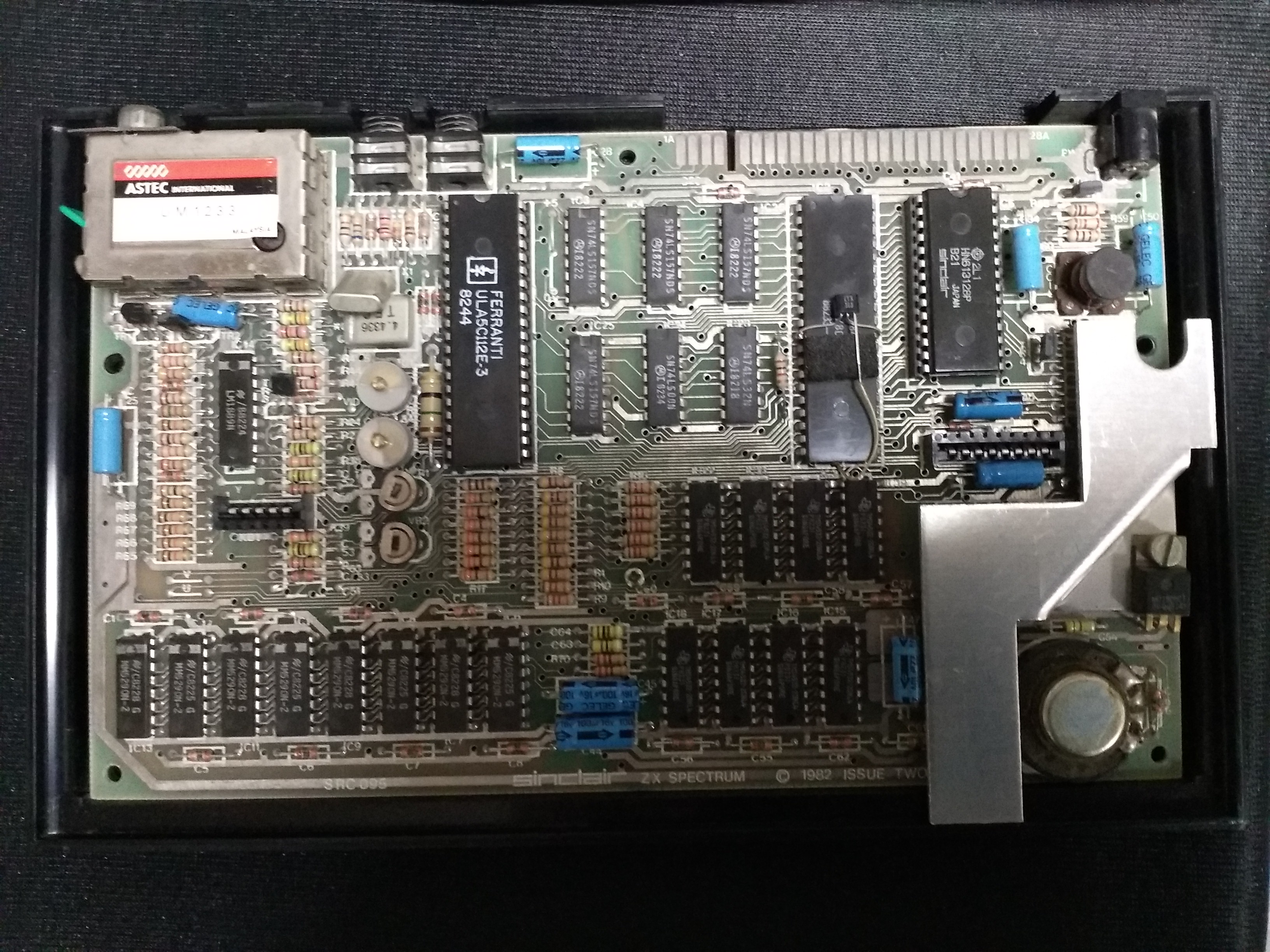
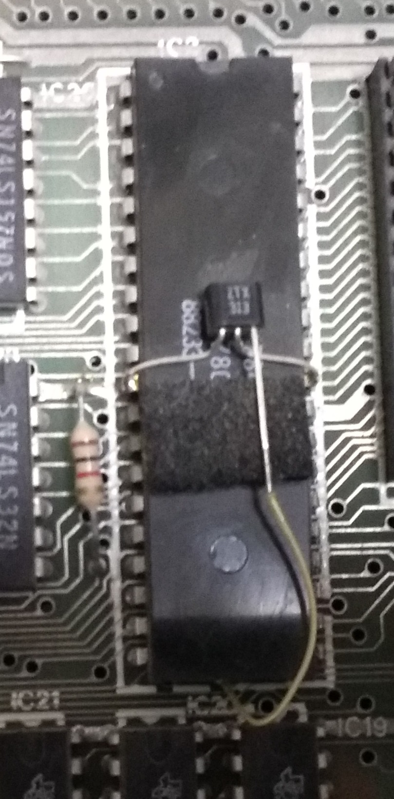
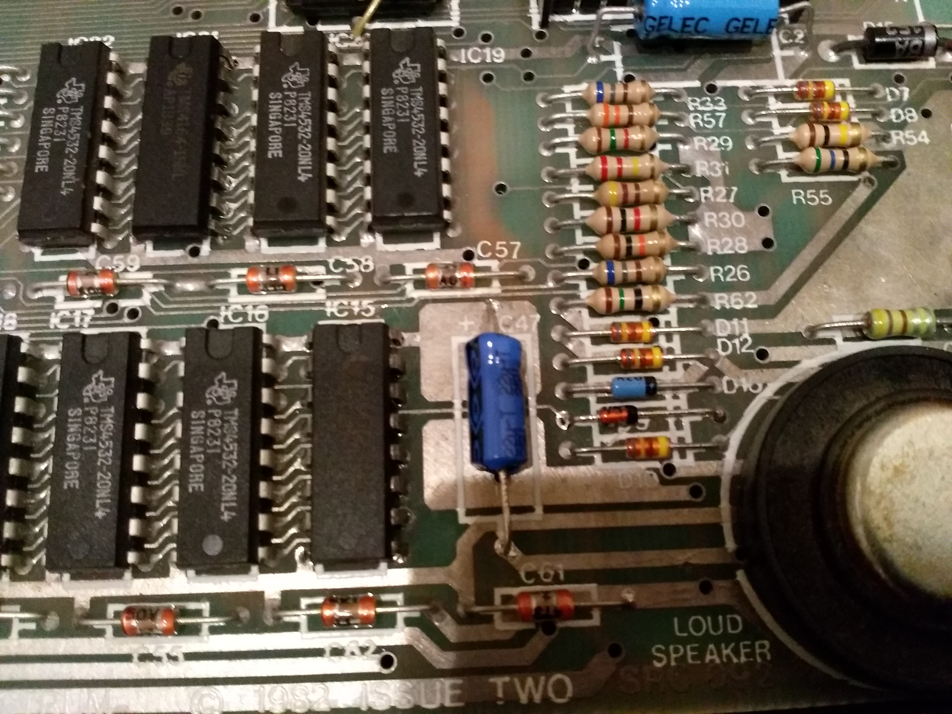
If some of the electrolytic capacitors have degraded, yes renewing them should help to improve the quality of the display.
How are you connecting to your TV / monitor?
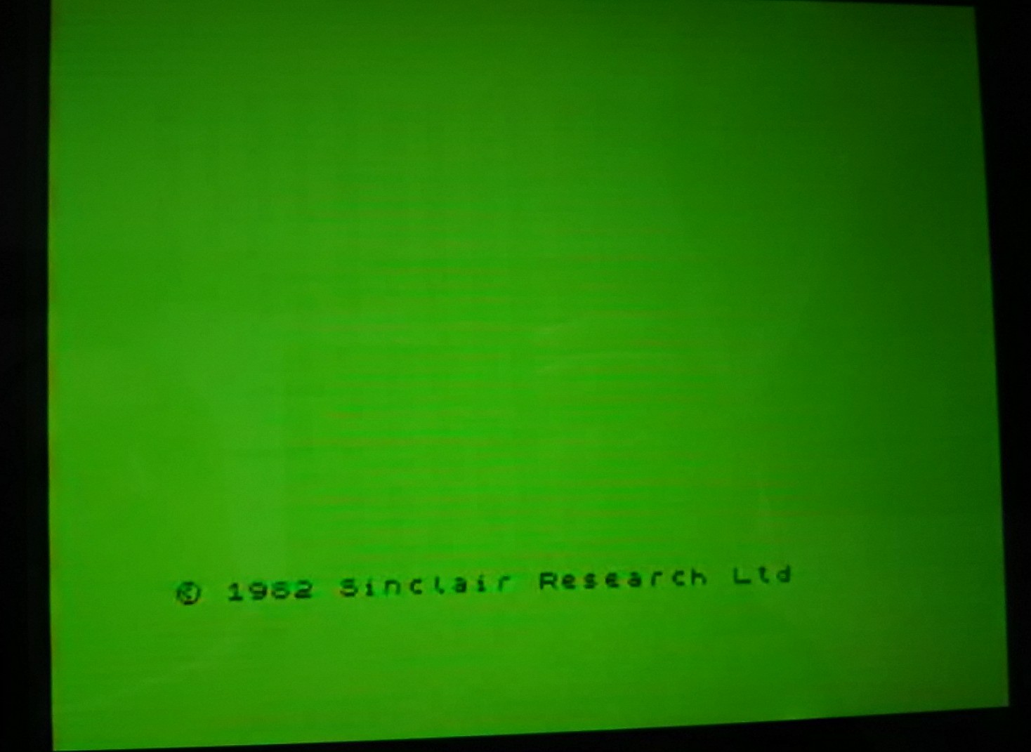
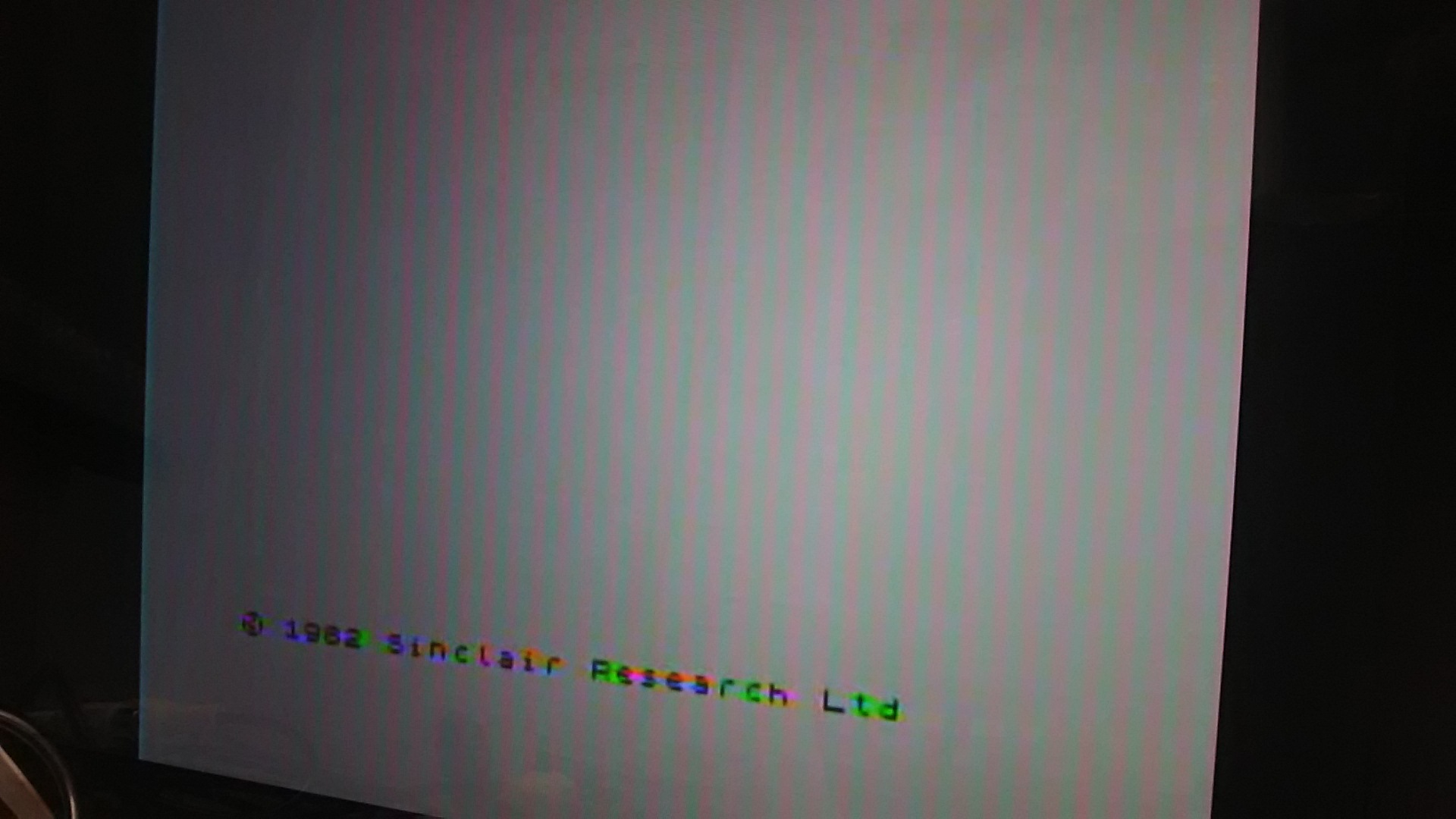
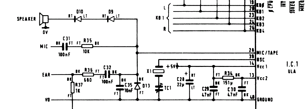
I recommend the composite video modification that uses a electrolytic capacitor. Even with this, due to limitations in the design of the ZX Spectrum, there will still be colour bleeding.
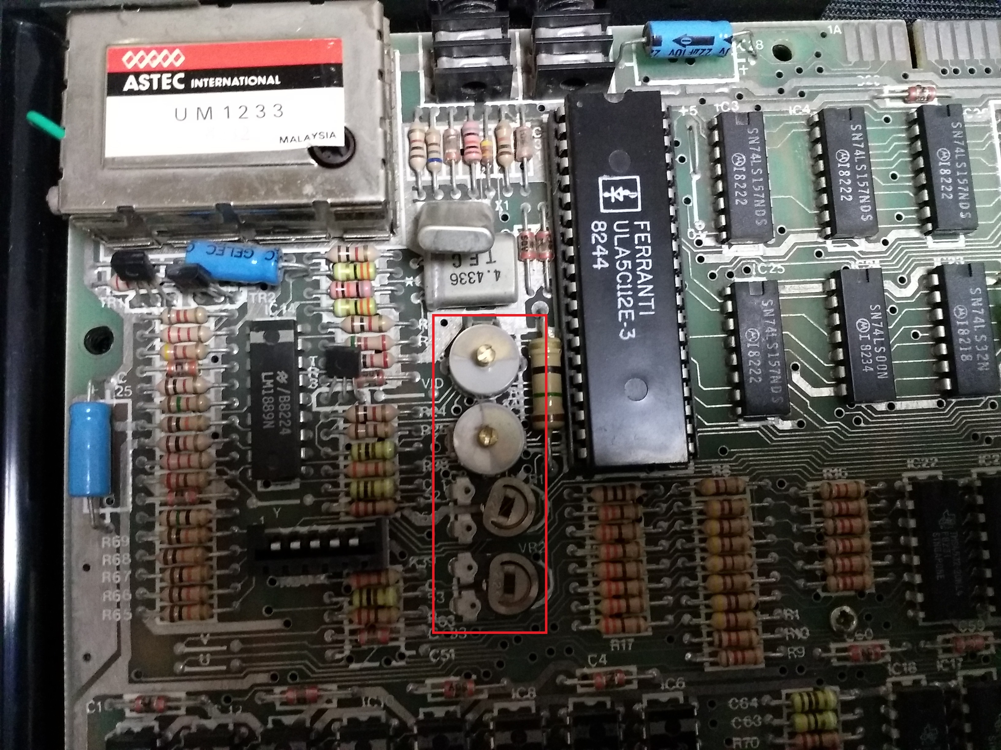
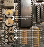
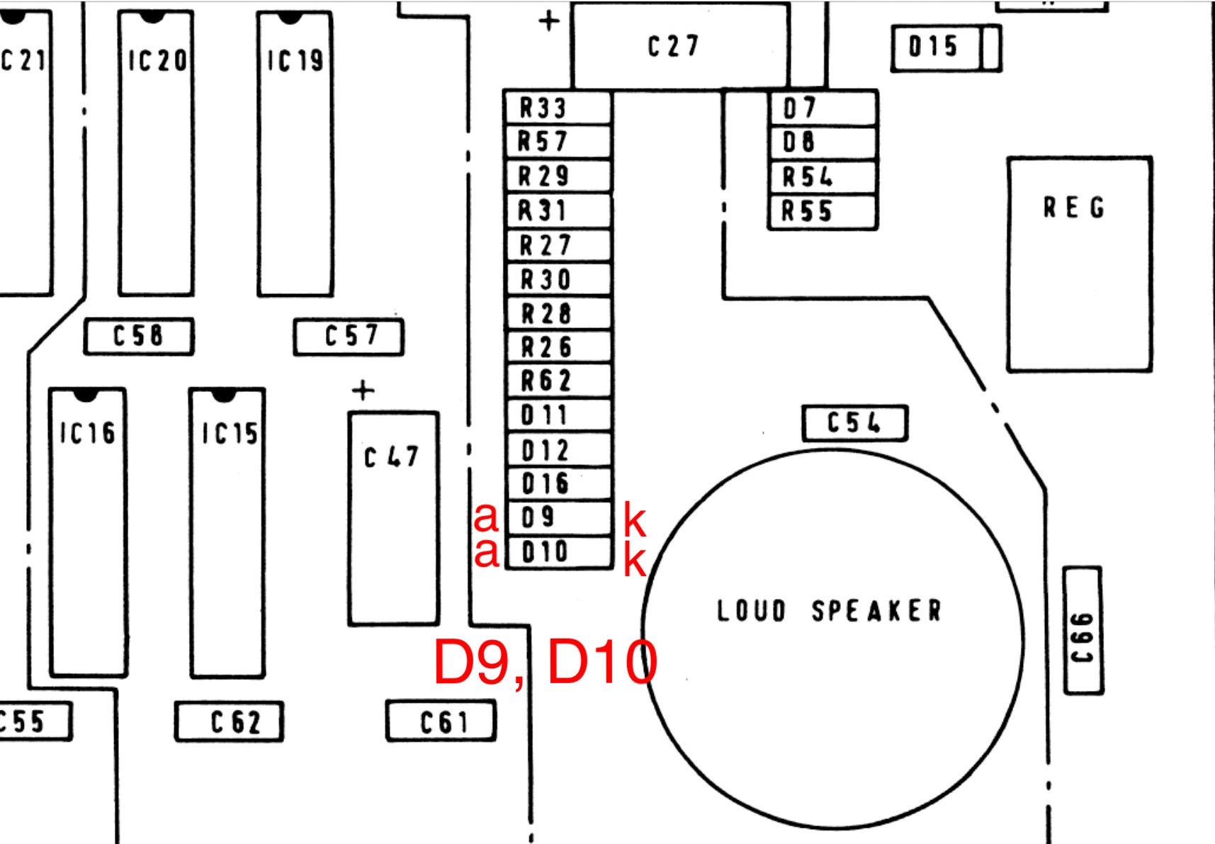
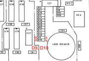
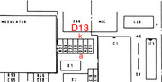
If you see faint vertical ‘bars’ (“jail bars”), then replace capacitors C5, C6, C7 and C8 with 470nF or 1uF multilayer ceramic types.
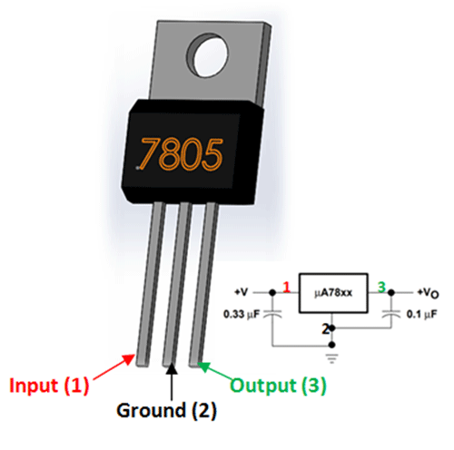
All the voltages you took, they are okay, all within the specifications

For your memory problems, first type this line in:
PRINT PEEK 23732 + PEEK 23733 * 256
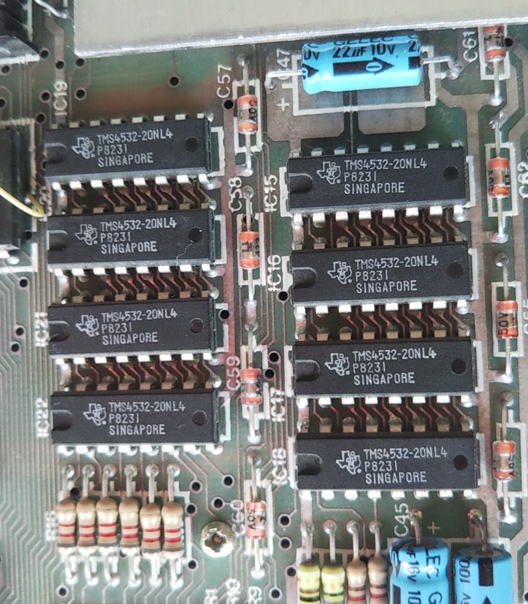
A machine that only has 16k bytes of working RAM should produce 32767. If a 48k machine produces this result, there is a fault with the ‘upper’/extension RAM.
A machine with 48k bytes of working RAM should produce 65535.
Any other result indicates there is a RAM fault.
Here is a quick and simple test program:
48K ZX Spectrum quick ‘n simple RAM test
1 CLEAR 24999
2 FOR a=25000 TO 65535 STEP 250
3 PRINT AT 0,0;a: POKE a,0: LET d=PEEK a: IF d<>0 THEN GO SUB 8
4 POKE a,255: LET d=PEEK a: IF d<>255 THEN GO SUB 8
5 NEXT a
6 PRINT “done”: STOP
8 PRINT “error at “;a;” “;d
9 RETURN
Type this in and run it.
For any of the addresses that are listed as having errors, then use:
RAM test, test one address only looking for a bit error
1 CLEAR 24999
2 PRINT “Enter address to test”
3 INPUT a : IF a<25000 THEN GOTO 3
4 PRINT “Address ”;a
5 FOR c=1 TO 4
6 READ t
7 POKE a,t: LET d=PEEK a
8 PRINT “Value written ”;t;“ value read ”;d
9 NEXT c
10 DATA 0,85,170,255
Alternatively you can use the cassette tape version of the ZX Spectrum diagnostic software.
Here’s a link to the site. The tape version is
here.
Mark


