1024MAK wrote: ↑Wed Feb 17, 2021 10:12 pm
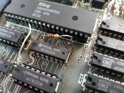
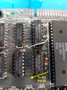
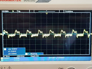
The 1kΩ resistor near the Z80 that goes between the +5V line and pin 32 on the ULA is R73 on later board issues. It is part of the Z80 clock circuitry. It’s a modification detailed in the service manual (see section 4.1). It’s fitted to improve the clock signal and therefore improve the system reliability.
Thanks for the info, I've found that in the service manual now. You wouldn't believe I've read it from start to finish, but obviously didn't absorb/retain that.

This has been done because the issue two board is only compatible with some types of DRAM chip. From the issue three boards onwards, the PCB and the circuitry was altered to allow DRAM chips from a different manufacturers to be used.
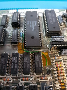
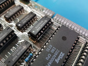
Aha! As you can see on the pic below this Speccy has OKI ram fitted. I'm assuming this mod has been carried out by a third party at some point, not sure the factory would have completed it in such a messy fashion?
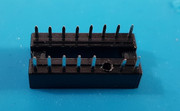
I'm going to see if I can re-instate it in a tidier way, the chip having its leg cocked up like it's doing the cancan at the Moulin Rouge offends my sense of order.

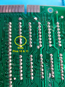
If I removed that pin on the socket, then attach a thin wire to the leg of the chip that can be passed down through the socket and the via to make a connection underneath the board. This would allow me to have the leg of the chip back in the socket, but not actually making electrical contact with the socket or the via underneath. It might work!
Not all issue two boards got the spider modification, or it may have been lost if the Z80 was replaced. Looking at the date code on the Z80 that’s fitted (made in 1987), I would say it’s the latter reason.
I seem to recall the mod was half hanging off, so I removed it with the intention of putting it back once the Speccy was working again.
Thanks for the advice, top notch guidance as always!